- 您现在的位置:买卖IC网 > Sheet目录2006 > LTC2382HMS-16#PBF (Linear Technology)IC ADC 16BIT 1CH 500KSPS 16-MSOP
LTC2382-16
17
238216f
TIMING DIAGRAM
238216 F13a
RDL2
RDL1
CONVERT
IRQ
DATA IN
DIGITAL HOST
CLK
CNV
LTC2382-16
SDO
A
SCK
RDL/SDI
CNV
LTC2382-16
SDO
B
SCK
RDL/SDI
CHAIN
BUSY
CHAIN
238216 F13
D15A
SDO
SCK
CNV
BUSY
CHAIN = 0
RDL/SDIB
RDL/SDIA
D15B
D14B
D1B
D0B
D13B
D14A
D13A
D1A
D0A
Hi-Z
tEN
tHSDO
tDSDO
tDIS
tSCKL
tSCKH
tCNVL
tHSCKRDL
tSSCKRDL
12
3
14
15
16
17
18
19
30
31
32
tSCK
POWER-UP
CONVERT
POWER-DOWN
CONVERT
ACQUIRE
tCONV
tHOLD
tBUSYLH
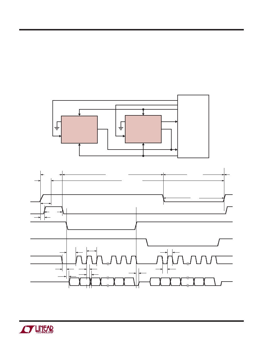
Figure 13. Normal Mode with Multiple Devices Sharing CNV, SCK and SDO
Normal Mode, Multiple Devices
Figure 13 shows multiple LTC2382-16 devices operating
in Normal Mode(CHAIN = 0) sharing CNV, SCK and SDO.
By sharing CNV, SCK and SDO, the number of required
signals to operate multiple ADCs in parallel is reduced.
Since SDO is shared, the RDL/SDI input of each ADC must
be used to allow only one LTC2382-16 to drive SDO at a
time in order to avoid bus conflicts. As shown in Figure 13,
the RDL/SDI inputs idle high and are individually brought
low to read data out of each device between conversions.
When RDL/SDI is brought low, the MSB of the selected
device is output onto SDO. To ensure the MSB is properly
output and captured, SCK must be held low at least 1ns
before and 16ns after bringing RDL/SDI low.
发布紧急采购,3分钟左右您将得到回复。
相关PDF资料
LTC2383HMS-16#PBF
IC ADC 16BIT 1CH 1MSPS 16-MSOP
LTC2393IUK-16#TRPBF
IC ADC 16BIT SER/PAR 1M 48-QFN
LTC2410IGN#TRPBF
IC ADC 24BIT DIFF INP/REF 16SSOP
LTC2411-1IMS#TRPBF
IC A/DCONV DIFF INPUT&REF 10MSOP
LTC2418IGN#TRPBF
IC ADC 24BIT DIFF INPUT 28SSOP
LTC2431IMS#TRPBF
IC ADC 20BIT DIFFINPUT/REF10MSOP
LTC2433-1IMS#TRPBF
IC ADC DIFF 16BIT 3WIRE 10-MSOP
LTC2435CGN#TRPBF
IC ADC DIFF I/REF 20BIT 16-SSOP
相关代理商/技术参数
LTC2382HMS-16#TRPBF
功能描述:IC ADC 16BIT 1CH 500KSPS 16-MSOP RoHS:是 类别:集成电路 (IC) >> 数据采集 - 模数转换器 系列:- 标准包装:1,000 系列:- 位数:12 采样率(每秒):300k 数据接口:并联 转换器数目:1 功率耗散(最大):75mW 电压电源:单电源 工作温度:0°C ~ 70°C 安装类型:表面贴装 封装/外壳:24-SOIC(0.295",7.50mm 宽) 供应商设备封装:24-SOIC 包装:带卷 (TR) 输入数目和类型:1 个单端,单极;1 个单端,双极
LTC2382IDE-16#PBF
功能描述:IC ADC 16BIT 1CH 500KSPS 16-DFN RoHS:是 类别:集成电路 (IC) >> 数据采集 - 模数转换器 系列:- 标准包装:1,000 系列:- 位数:12 采样率(每秒):300k 数据接口:并联 转换器数目:1 功率耗散(最大):75mW 电压电源:单电源 工作温度:0°C ~ 70°C 安装类型:表面贴装 封装/外壳:24-SOIC(0.295",7.50mm 宽) 供应商设备封装:24-SOIC 包装:带卷 (TR) 输入数目和类型:1 个单端,单极;1 个单端,双极
LTC2382IDE-16#TRPBF
功能描述:IC ADC 16BIT 1CH 500KSPS 16-DFN RoHS:是 类别:集成电路 (IC) >> 数据采集 - 模数转换器 系列:- 标准包装:1,000 系列:- 位数:12 采样率(每秒):300k 数据接口:并联 转换器数目:1 功率耗散(最大):75mW 电压电源:单电源 工作温度:0°C ~ 70°C 安装类型:表面贴装 封装/外壳:24-SOIC(0.295",7.50mm 宽) 供应商设备封装:24-SOIC 包装:带卷 (TR) 输入数目和类型:1 个单端,单极;1 个单端,双极
LTC2382IMS-16#PBF
功能描述:IC ADC 16BIT 1CH 500KSPS 16-MSOP RoHS:是 类别:集成电路 (IC) >> 数据采集 - 模数转换器 系列:- 标准包装:1,000 系列:- 位数:12 采样率(每秒):300k 数据接口:并联 转换器数目:1 功率耗散(最大):75mW 电压电源:单电源 工作温度:0°C ~ 70°C 安装类型:表面贴装 封装/外壳:24-SOIC(0.295",7.50mm 宽) 供应商设备封装:24-SOIC 包装:带卷 (TR) 输入数目和类型:1 个单端,单极;1 个单端,双极
LTC2382IMS-16#TRPBF
功能描述:IC ADC 16BIT 1CH 500KSPS 16-MSOP RoHS:是 类别:集成电路 (IC) >> 数据采集 - 模数转换器 系列:- 标准包装:1,000 系列:- 位数:12 采样率(每秒):300k 数据接口:并联 转换器数目:1 功率耗散(最大):75mW 电压电源:单电源 工作温度:0°C ~ 70°C 安装类型:表面贴装 封装/外壳:24-SOIC(0.295",7.50mm 宽) 供应商设备封装:24-SOIC 包装:带卷 (TR) 输入数目和类型:1 个单端,单极;1 个单端,双极
LTC2383CDE-16#PBF
功能描述:IC ADC 16BIT 1CH 1MSPS 16-DFN RoHS:是 类别:集成电路 (IC) >> 数据采集 - 模数转换器 系列:- 标准包装:1,000 系列:- 位数:12 采样率(每秒):300k 数据接口:并联 转换器数目:1 功率耗散(最大):75mW 电压电源:单电源 工作温度:0°C ~ 70°C 安装类型:表面贴装 封装/外壳:24-SOIC(0.295",7.50mm 宽) 供应商设备封装:24-SOIC 包装:带卷 (TR) 输入数目和类型:1 个单端,单极;1 个单端,双极
LTC2383CDE-16#TRPBF
功能描述:IC ADC 16BIT 1CH 1MSPS 16-DFN RoHS:是 类别:集成电路 (IC) >> 数据采集 - 模数转换器 系列:- 标准包装:1,000 系列:- 位数:12 采样率(每秒):300k 数据接口:并联 转换器数目:1 功率耗散(最大):75mW 电压电源:单电源 工作温度:0°C ~ 70°C 安装类型:表面贴装 封装/外壳:24-SOIC(0.295",7.50mm 宽) 供应商设备封装:24-SOIC 包装:带卷 (TR) 输入数目和类型:1 个单端,单极;1 个单端,双极
LTC2383CDE-16PBF
制造商:Linear Technology 功能描述:ADC 16-Bit 1Msps Low Power SPI DFN16